CambridgeIC will be at SPS – Smart Production Solutions 2026 in Nuremberg from November 24 to 26. Visit us in Hall 4, Booth 174, where we are exhibiting with MEV.
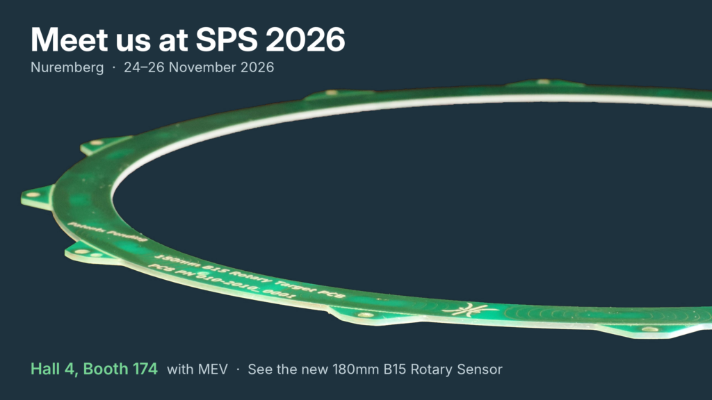
On the stand you can see our new 180mm B15 Rotary Sensor and matching target, the largest in our Type B Rotary Sensor family. Their large centre holes take a rotating shaft of up to 156mm diameter, and together the sensor and target are only 2.5mm thick. They give full absolute angle measurement with linearity error below ±0.01°, rising only to ±0.023° under gap, radial and tilt misalignment, with no calibration needed.
We’ll also be demonstrating the CAM622 processor, which works with all our Type B sensors and offers SPI, quadrature ABN, BiSS and SENT interfaces.
SPS is a great opportunity to discuss your application with our engineers, whether you’re:
Designing high-speed closed-loop motion control
Sensing valve position
Building direct drive torque motors
Looking to replace optical or magnetic encoders with a lower-cost, more robust alternative
To arrange a meeting at the show, please contact us. We look forward to seeing you in Nuremberg!
CambridgeIC, founded in 2007, develops processor ICs for resonant inductive sensing technology. The team has been pioneering this technology since 1994 and today serves a wide range of customers in industrial, medical, and automotive applications, including market leaders in their fields.
CambridgeIC launches its largest rotary sensor yet
News
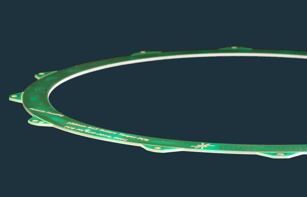
CambridgeIC has developed a new 180mm B15 Rotary Sensor and matching target for precise and accurate angle sensing. Both the sensor and target have a large centre hole that accommodates a rotating shaft of up to 156mm diameter.
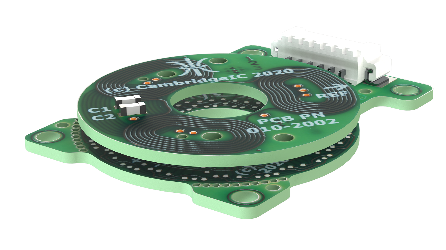
Like the smaller sensors in the Type B Rotary Sensor family, the sensor and target comprise coils printed on a PCB to CambridgeIC’s designs. Customers use these designs to build production parts themselves, to yield a precise, accurate, robust, environmentally immune angle sensing solution. Sensors work with CambridgeIC’s CAM622 processor, allowing customers to deeply integrate angle sensing within their machines.
The matching 180mm B15 Rotary target illustrated above is mounted on the rotating part. The sensor detects its angle using resonant inductive sensing technology without contact, and at a gap of between 0.5mm and 4mm.
When aligned at 1mm gap, the CAM622 reports position to a host device with 17.4 bits of noise free resolution. This is a true noise free figure, based on 0.002° peak to peak noise with default CAM622 motion filter settings. Many suppliers quote interface resolution instead, which for the CAM622 would be 32 bits.
Linearity error is less than ±0.01° when aligned at 1mm gap. This only increases to ±0.023° when gap is allowed to vary up to 4mm, radial misalignment up to 0.5mm and tilt up to 0.1°. This accuracy and tolerance to misalignment come from the inherent balance and quality of the designs, and the precision of PCB fabrication. This in turn makes the sensor and target easy to install, with no precise alignment or calibration necessary.
The sensor and target coil portions are only 10mm wide radially, yet they give a full absolute measurement. Each is built on a 1mm thick PCB, so with the minimum 0.5mm gap they occupy a total thickness of only 2.5mm.
The CAM622’s interface options include:
SPI
Quadrature ABN interface, configurable up to 65536 edges per revolution
BiSS (BiSS is a trademark of iC-Haus GmbH)
SENT
Applications include:
High-speed closed-loop motion control
Valve position sensing
Direct drive torque motors
Replacement of optical encoders
Reduce cost
Improve robustness and environmental immunity
Replacement of magnetic position encoders
Eliminate the magnetised target, which can attract swarf and is expensive
Improve immunity to magnetic fields from a nearby motor
Reduce the space envelope required for a full absolute angle measurement
Please contact us for more information or to purchase samples.
Visit us at SPS 2026 in Nuremberg from November 24 – 26 to see the new sensor and discuss applications! We are exhibiting with MEV in Hall 4, Booth 174.
CambridgeIC, founded in 2007, develops processor ICs for resonant inductive sensing technology. The team has been pioneering this technology since 1994 and today serves a wide range of customers in industrial, medical, and automotive applications, including market leaders in their fields.
CambridgeIC Launches Linear Sensors Compatible with CAM622 Processor
Newsflash
CambridgeIC is pleased to announce its new range of Type B Linear Sensors. These sensors combine robustness, precision, reliability, and low cost, thanks to their manufacture using a conventional PCB process.
CambridgeIC is pleased to announce its new range of Type B Linear Sensors. These sensors combine robustness, precision, reliability, and low cost, thanks to their manufacture using a conventional PCB process.
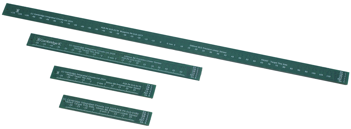
The new sensors incorporate special coil designs from CambridgeIC. Currently available designs support measuring lengths of 40mm, 50mm, 100mm, 150mm and 200mm. Each sensor coil includes an excitation coil to energize the target, coarse sensor coils to establish absolute position, and fine sensor coils for precision and accuracy.
A distinctive feature of the technology is that customers can manufacture sensors themselves using designs provided by CambridgeIC, helping to reduce manufacturing costs. The sensors detect the position of a moving, contactless target, which itself is also a PCB containing a resonant circuit with a printed coil and resonating capacitor(s). By making the target resonant, the system generates far stronger signals than conventional non-resonant inductive sensors—enabling high resolution, high accuracy, large operating gaps, and no need for calibration.
Signal processing is handled by CambridgeIC’s CAM622 Resonant Inductive Position Encoder IC. The CAM622 provides:
SPI interface, delivering typically 1μm noise-free resolution and full absolute position
Quadrature ABN interface, configurable down to 2μm AB edge resolution
Newly announced BiSS-C interface support (BiSS is a trademark of iC-Haus GmbH).
With these features, CambridgeIC’s Type B linear sensors offer the speed and resolution of optical encoders, but at a lower cost and with greater robustness and environmental immunity. Embedding the sensors and targets in a customer’s product is straightforward, requiring only normal engineering tolerances and no special alignment.
Unlike magnetic linear encoders, Type B sensors provide full absolute sensing at power-on, operate with small track widths, and the target does not attract magnetic swarf.
Key applications include:
High-speed closed-loop motion control
Linear motor feedback and commutation
Valve position sensing
Steering rack position sensing in vehicles
Replacement of optical and magnetic position encoders
CambridgeIC, founded in 2007, develops processor ICs for resonant inductive sensing technology. The team has been pioneering this technology since 1994 and today serves a wide range of customers in industrial, medical, and automotive applications, including market leaders in their fields.
CambridgeIC’s new CAM622 turns PCBs into precise angle encoders
Newsflash
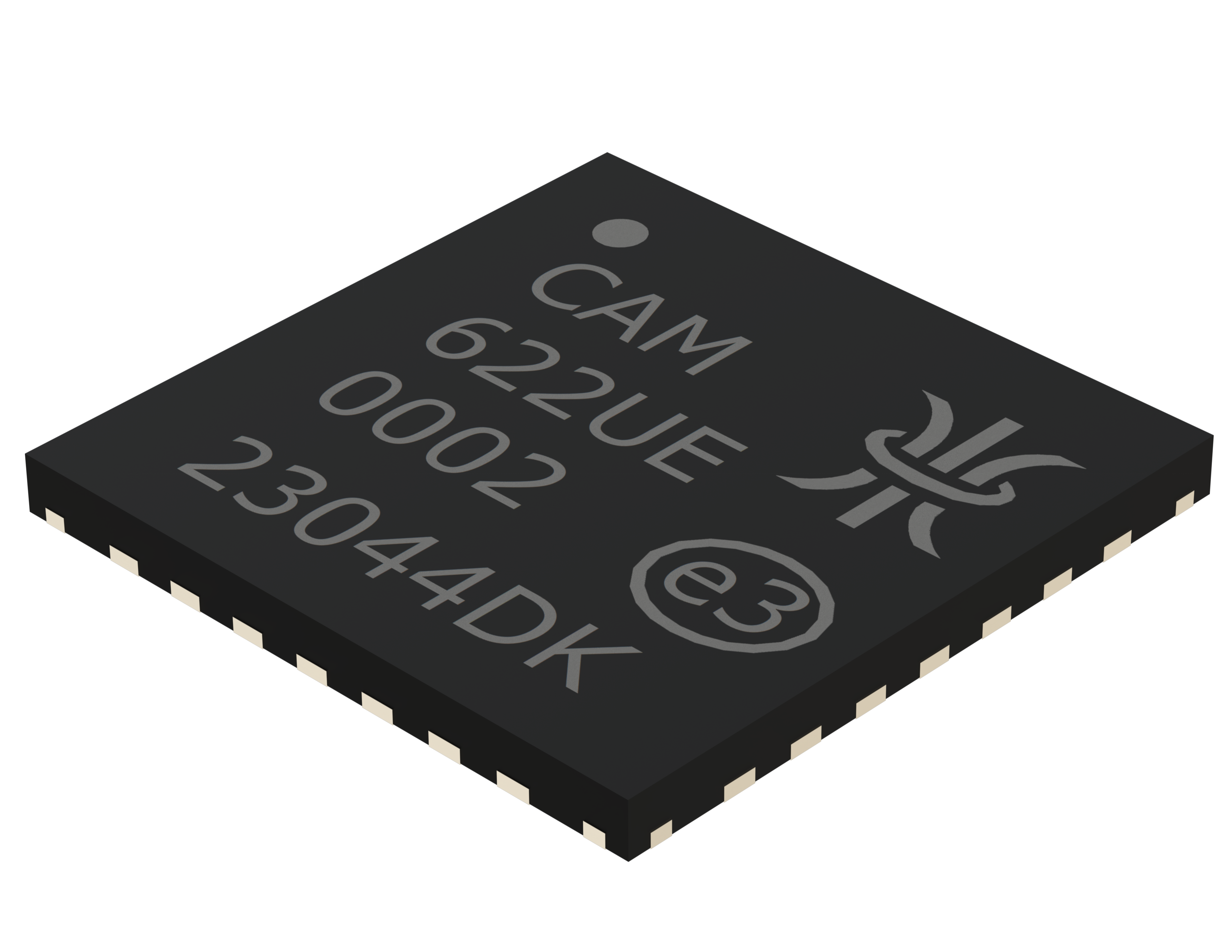
The CAM622 is a resonant inductive encoder IC for the measurement of angular position inside machines. It delivers an unparalleled combination of precision, speed and convenience, and helps customers reduce the size and cost of their products.
The CAM622 is a resonant inductive encoder IC for the measurement of angular position inside machines. It delivers an unparalleled combination of precision, speed and convenience, and helps customers reduce the size and cost of their products.
The CAM622 connects to a sensor, measures the angle of a contactless rotating target, and generates industry standard quadrature encoder ABN outputs in response. Like CambridgeIC’s existing processor ICs, sensors comprise special coil patterns manufactured using standard PCB fabrication. CambridgeIC designs compatible sensors and makes them available to customers. This approach makes sensors robust, precise, compact and cost effective to manufacture.
The CAM622 extends these benefits to the manufacture of targets. By increasing the operating frequency and reducing the minimum allowable quality factor of the resonator, the CAM622 is able to work with targets built from coils on a PCB. Targets comprise a disc shaped PCB with two surface mounted capacitors that form a resonant circuit. Resonant targets achieve far greater performance and gaps than standard inductive position sensing, and they eliminate the need for calibration. A range of sensors and targets is available, including outside diameters of 25mm, 30mm and 50mm. These have progressively larger centre holes, with the 50mm B5 sensor and target able to accommodate a 30mm diameter through shaft.
The new style of sensors and their matching targets are referred to as Type B Sensors and Type B Targets. Like CambridgeIC’s existing technology, there is no need for precise alignment when mounted inside a customer’s product. Type B Sensors and Targets are both designed with a high degree of balance and symmetry. For example, the 25mm B3 Sensor achieves better than ±0.14° linearity error when the gap between sensor and target is between 0 and 2mm, with ±0.3mm radial and ±0.3° tilt misalignments. By accommodating such large misalignments, the technology gives customers the freedom to use conventional mounting methods such as screws, which further reduces integration cost.
The CAM622 includes circuitry to generate quadrature ABN outputs at up to 16 bit angular resolution. This means it can replace optical encoders, eliminating any accompanying bearings, seals and housings. The resulting mechanical assembly is far simpler, delivering a more cost effective measurement solution overall. Furthermore, the CAM622’s ABN outputs are fully programmable, including cycles per revolution and N pulse position. A single hardware design can support multiple applications with only software customisation, without the need for multiple hardware variants and mechanical adjustment.
To meet the needs of even the most dynamic control systems, the CAM622 features an internal sample rate of 33,000 independent measurements per second. This is more than 6 times faster than the previous benchmark set by the CAM502. The frequency of the CAM622’s ABN ouptuts updates every measurement. This ensures that the ABN count value keeps pace with actual position, even under extreme acceleration. As for extreme rotational velocities, the CAM622 is tested at up to 66,000rpm with the 25mm B3 Sensor.
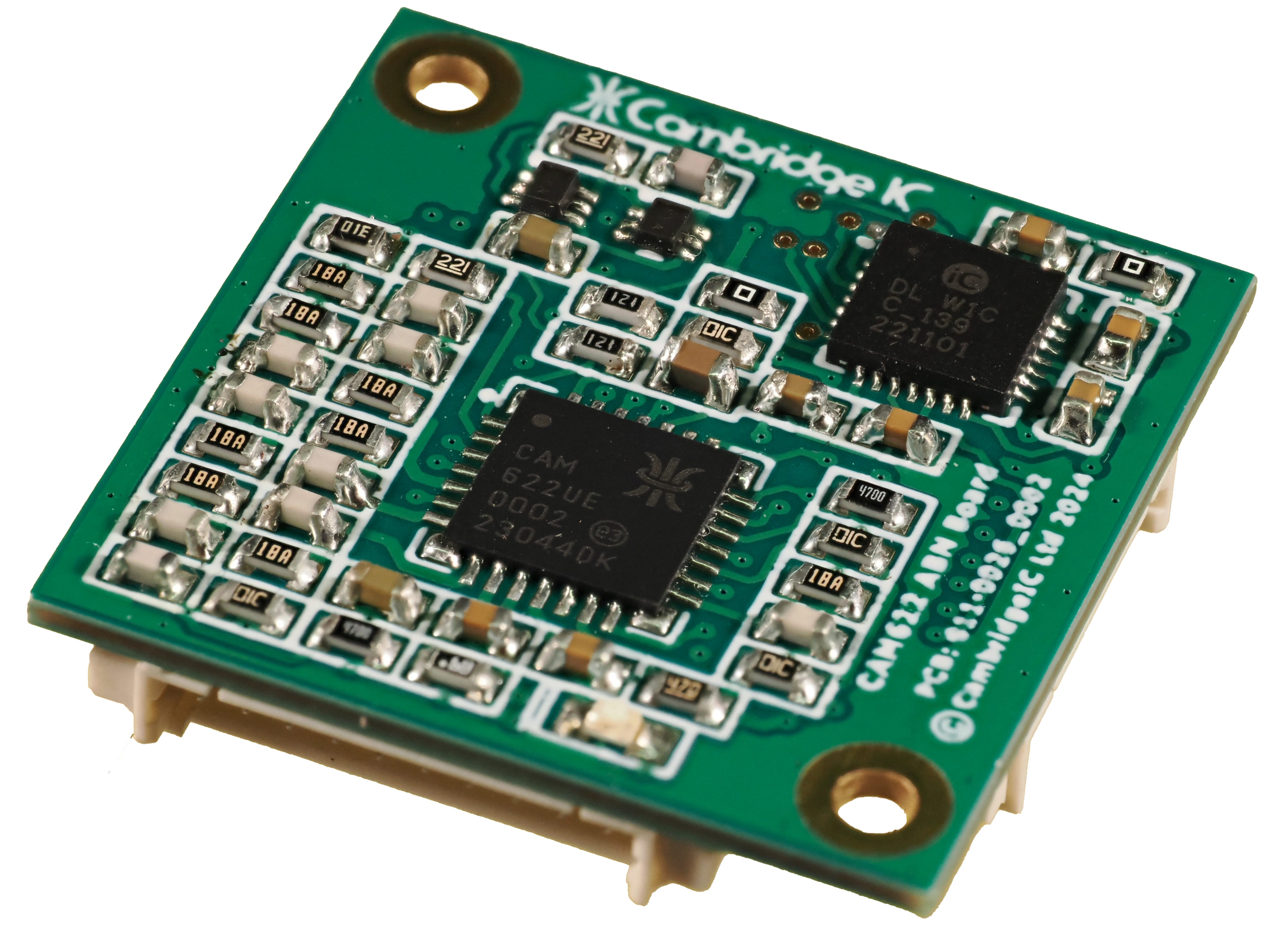
A CAM622 ABN Board is available. This connects to any of the new Type B sensors. It includes the CAM622 processor together with external circuitry to deliver differential ABN outputs from a 5V supply.
The CAM622 will be on show in public for the first time at the SPS show in Nuremberg from 12 – 14 November. For a demonstration, visit CambridgeIC at in Hall 4, stand 174, where we will be joining our distributor MEV.
Unique axial linear position sensor from CambridgeIC works with a free rotating target
Newsflash
CambridgeIC has released a new axial linear position sensor which works with a rotating target and a big gap to the sensor.
CambridgeIC has released a new axial linear position sensor which works with a rotating target and a big gap to the sensor.
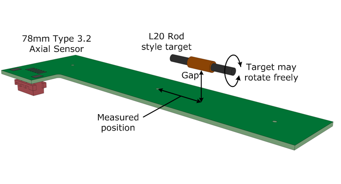
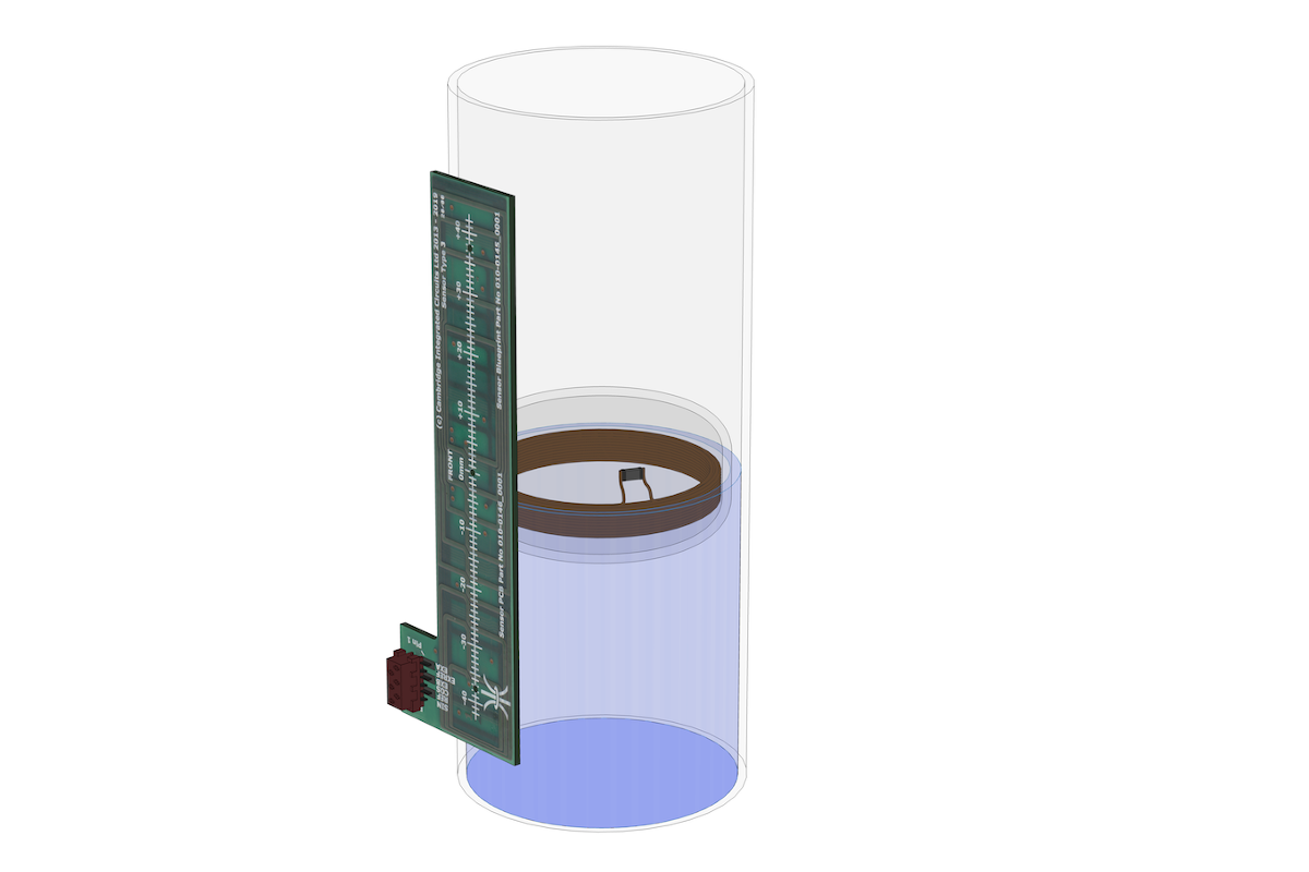
The new Axial sensors are unique in measuring the precise continuous position of a freely rotating wireless target, from the side and with a big gap, and without interference from nearby magnets. Gaps of over 10mm are possible between sensor and target. This means both the sensor and the target can be housed inside their own plastic housings. A target’s position can be sensed from outside the box containing the sensor.
Axial sensors offer product designers new opportunities to eliminate mechanical complexity and cost. Applications include valve control, hydraulic and pneumatic actuator position feedback, liquid level and syringe plunger position sensing.
They can tolerate substantial misalignment. In the float level sensing application this means the float can move side to side with big clearances, so there is no risk of it becoming stuck in the float tube. Tolerance to angular misalignment means the liquid can slosh around with an angled surface level, which is important for applications in moving vehicles.
In applications such as measuring the linear position of valves and pistons, tolerance to misalignment means the sensor and target do not require precise mounting. There is no need to add a special linear bearing to constrain the motion of the target.
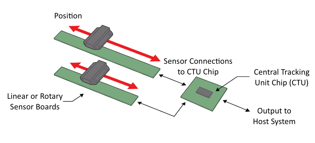
To calculate position the sensor works with CambridgeIC’s CAM312 central tracking unit. This chip measures and processes sensor signals, and provides high quality position data to a host device over an SPI interface.
CambridgeIC’s resonant inductive position sensing technology is well proven across a wide range of high-volume applications worldwide. Using PCBs to build position sensors makes them robust and tolerant of temperature changes, dirt, moisture, vibration and shock. The inherent accuracy of modern PCB fabrication delivers high sensor accuracy.
Customers can build sensors themselves, for cost effective and convenient production. It also allows designers to add their own circuitry to the same PCB, eliminating connectors and other parts and further simplifying production.
CambridgeIC’s team has been developing resonant inductive position sensing solutions since 1995. CambridgeIC launched the world’s first commercially available resonant inductive processor IC in 2010.
Find out more or download a datasheet at www.cambridgeic.com/products/linear-sensors/axial-linear-sensors. For test and evaluation an axial sensor development kit is also available, see www.cambridgeic.com/products/dev-tools/axial-sensor-development-kit.
Resolvers have become the technology of choice for traction motor feedback, particularly in automotive applications. The construction is relatively simple, they operate largely without wear and tolerate extreme environments well. Recently a new approach is gaining traction: resonant inductive position sensors have much in common with resolvers, being based on the same physical principles, but use printed coils and PCB technology to capture position data.
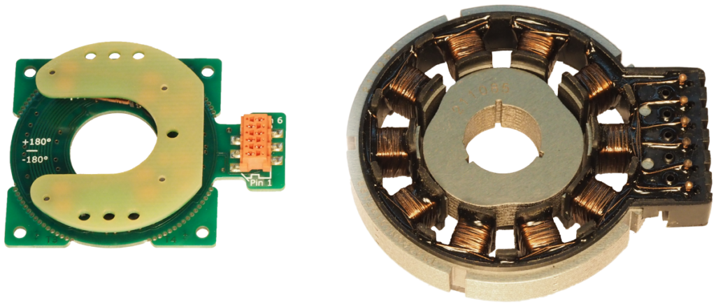
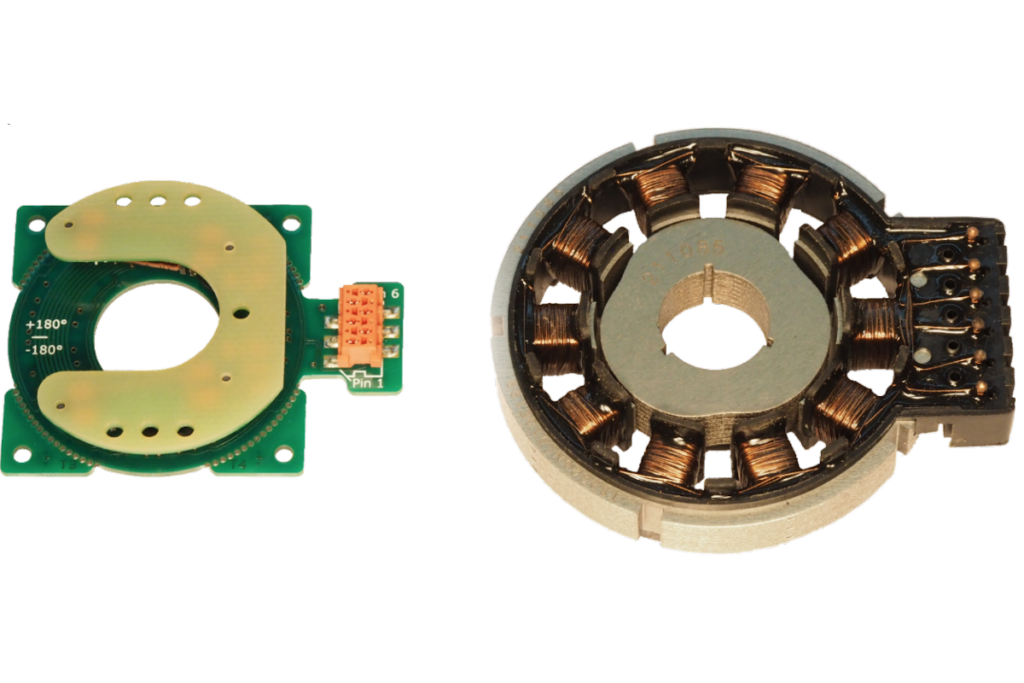
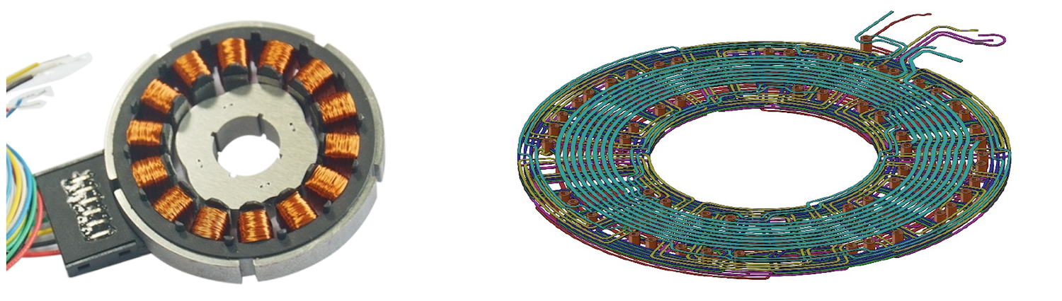
35mm Type 6.3 Rotary Sensor (left) and 52mm VR Type Resolver (right)
This delivers a number of advantages:
Improvements in accuracy, for efficiency and smoothness
Reduced cost, by using simpler components that are easier to manufacture
Greater tolerance to misalignment, for ease of installation and lower cost
Physically smaller parts
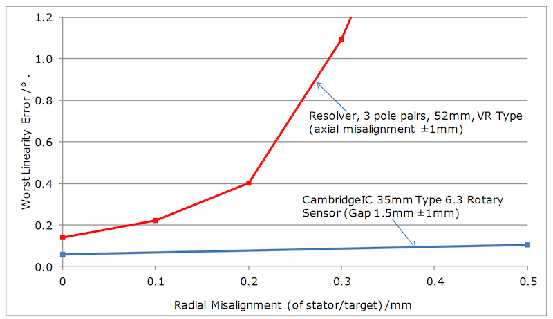
Linearity error comparison, typical parts.
In motor control applications, these differences can have significant impact on performance in such areas as motor efficiency and speed of feedback in dynamic systems.
Our latest white paper Resonant Inductive Sensing Vs Resolvers looks at the differences in construction and performance and what that means for motor applications. Download it using the link above, or get in touch with us to discuss the findings.
What is the difference between a Resonant Inductive Sensor and a Resolver?
Newsflash
Compact, light, cost effective; how resonant inductive sensing compares to resolvers.
Compact, light, cost effective; how resonant inductive sensing compares to resolvers.
CambridgeIC’s team has led the development of resonant inductive sensing solutions for more than 20 years, producing solutions for a wide range of industrial applications.
Compared to a resolver, this approach allows for a more compact, light and cost effective solution, ideal for integrating into designs. This short white paper summarises the similarities and differences between the two approaches.
Shared features of resonant inductive and resolvers
Both determine position by measuring inductive coupling factors between a moving target/rotor and fixed sensor/stator.
Both have coupling factors vary sinusoidally with angle and at least 2 phases of sensor coils and include an atan2(cos_coupling, sin_coupling) function for determining position.
Both are robust and suited to a harsh engine environment
Differences
Fig1. Resolver “motor-like” wound construction (left) and resonant inductive coils build on a PCB (right)
Resonant inductive sensors are usually built from a PCB while resolvers are wound components constructed like a motor
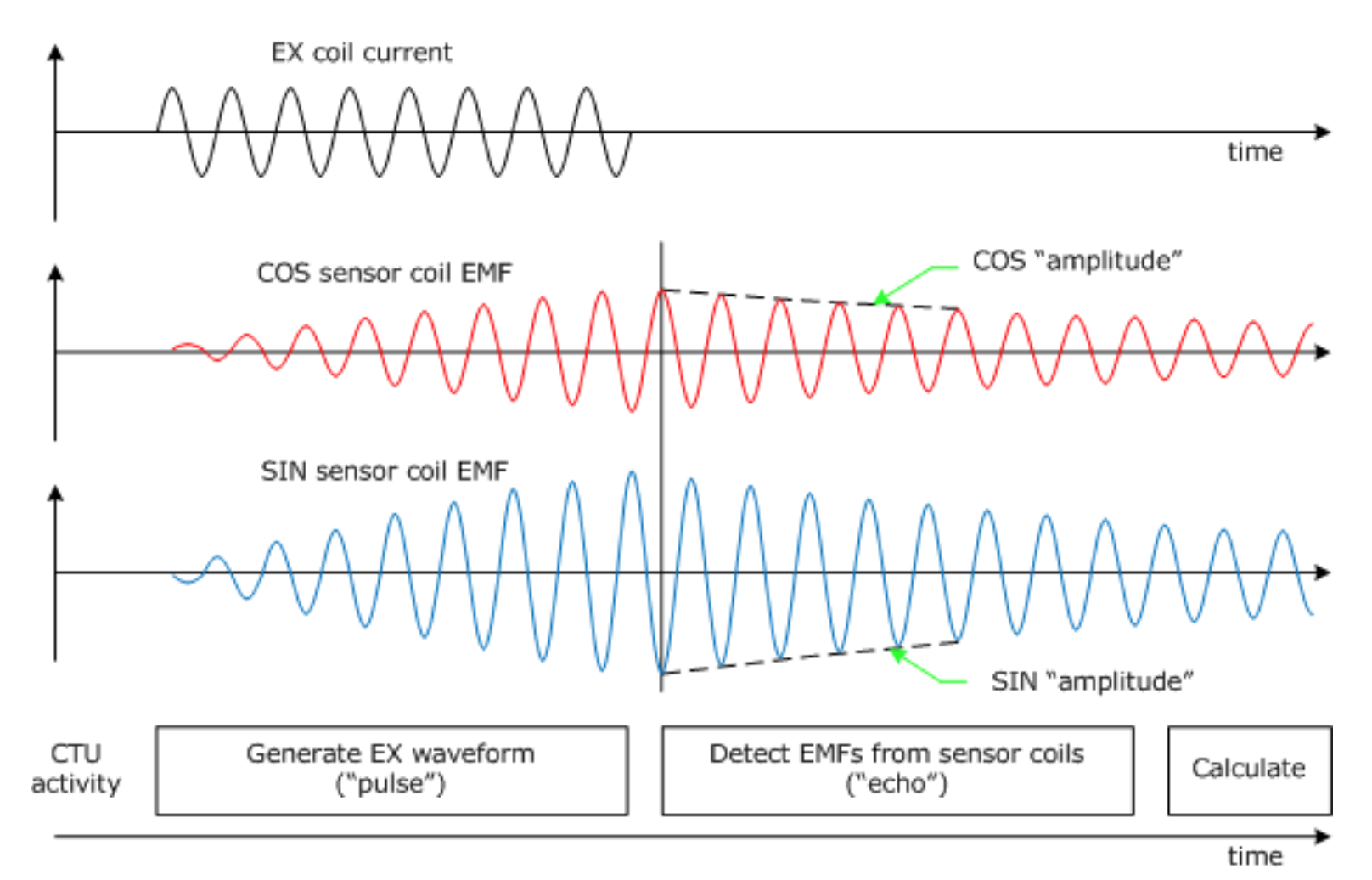
Resonant inductive sensors use a resonant target with relatively high Q factor, so that the target can be excited by current in the sensor separately to receiving signals back from it (“pulse echo”). This means there is no chance of the “breakthrough” that resolvers suffer from, which is an important cause of linearity errors, especially when misaligned. See Fig 2 and also https://www.cambridgeic.com/technology/interrogation.
Fig 2: Sequence of events in a pulse echo cycle for Resonant Inductive System
Resonant inductive sensors operate at a higher frequency, while the steel in a traditional resolver prevents operation at high frequencies.
Resonant inductive sensors have a much lower impedance than resolvers due to having only a few coil turns.
Advantages of resonant inductive sensors
Fundamentally lower cost sensor and target
Sensor and target can use standard PCB fabrication/assembly from any convenient manufacturer, and are not tied to a specialist supplier
Lower linearity error due to greater scope for design optimisation, including when sensor and target are misaligned form the rotation axis.
Lower linearity error due to “pulse echo” sensor interrogation, so that it is easier to suppress once per revolution position errors.
Fewer analog components external to processor. This is because passive (RC) filters can be used in place of active (op-amp) filters, because the sensor coils have a low impedance.
Sensor can include “fine” and “coarse” sensor coil pairs for an output that is full absolute across 360° of rotation (from “coarse” coils with one pole pair per revolution) while still achieving high accuracy and resolution (from multi-pole “fine” sensor coils). In some applications absolute 360° is a requirement. However even if it isn’t, it can help indirectly, for example by allowing the customer to infer how error changes across a full 360° and hence correct for that error and deliver greater drive smoothness.
Fundamentally lower group delay between actual angle and angle reported to motor controller, due to higher operating frequency, so that velocity and position control loops can have higher bandwidth and/or margins and perform better.
Resonant inductive sensors and targets have more design flexibility, allowing a tighter and more optimised integration with the customer’s machine.
Disadvantages of resonant inductive sensors
A faster ADC rate is required to digitise the incoming sensor signals
It takes more digital signal processing to process sensor signals because the detected frequency is a variable (equal to the target’s resonator frequency) and not fixed (the same as the excitation frequency)
They use a higher excitation frequency, so the waveform edges used to excite the sensor need to be adequately slowed down to suppress electrostatic emissions
They’re a recent technology (~ 10 years) and don’t have the deep history of resolvers (~70 years)
Find out more
This white paper is intended to provide background and guidance; for more detailed insights and assistance with questions on resonant inductive sensing and whether it is suitable for your application, get in touch with CambridgeIC’s engineers using our live chat or email links.
While we were at the SPS show recently we took the opportunity to shoot a short video that demonstrates the basic operation of a CambridgeIC system.
While we were at the SPS show recently we took the opportunity to shoot a short video that demonstrates the basic operation of a CambridgeIC system.
We take a short look at how resonant inductive position sensing works, how our customers work with us and why.
Turns out a noisy show isn’t the easiest place to record a conversation, so we’ve also transcribed the video below. The next demo video will be shot in a quieter location!
Transcript:
Hello I am Guido Gandolfo, Product Manager with MEV, and we are here at the booth from MEV at the SPS show in Nuremberg, Germany. And with me is David Ely, hi David!
And I’m director of Cambridge Integrated Circuits, CambridgeIC in Cambridge England.
Welcome to our booth, and you wanted to show me what products you bought.
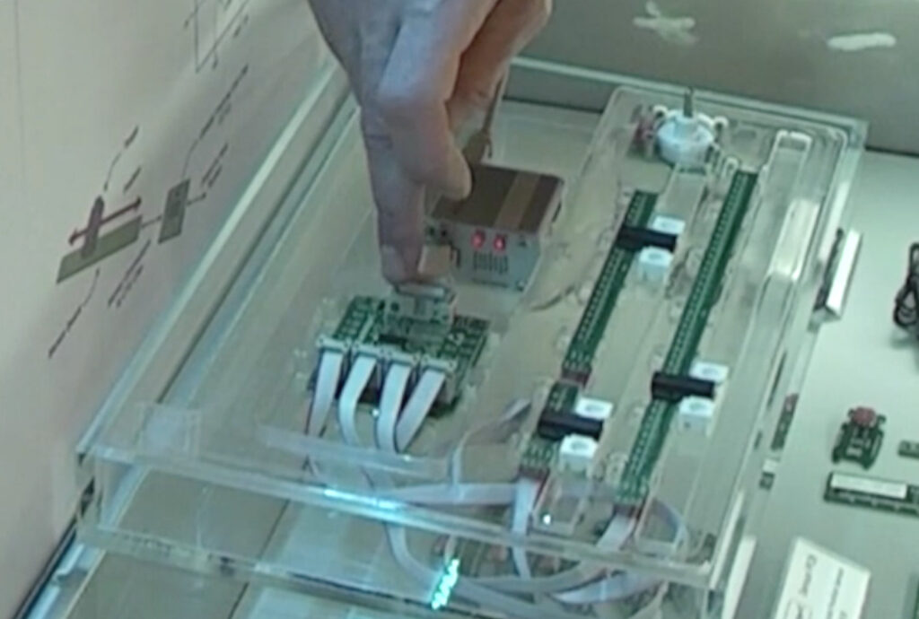
Of course yes. So this is our development kit here and this is demonstrating our CAM204 chip working with three linear and one rotary inductive position sensors connected back to the chip. And this chip is reporting the position of one, two, three, four sensors – three linear and one rotary. It’s a non contacting sensor so I can remove them and put them back – they will operate across the gap between the sensor and the target. I can increase the gap on this target and the sensor still works, so its full non contact.
So all of these sensors are made from printed circuit boards. They’re connected back to the CAM204 chip and the principle of operation is, inside these targets is a resonant circuit, a little inductor and capacitor and the chip energises them by sending current through the sensor coils which creates a magnetic field which energises the targets and then the sensor listens back for signals from the targets and those pass back to the chip, the chip processes those signals, calculates position and then sends it over a digital interface – in this case this is an interface box for a PC but for a normal customer application this would be connected to a microprocessor, micro controller inside the product.
OK that’s very interesting. So the sensor is only a PCB, is that right?
That’s all there is to it, a PCB measuring the position of, in this case, what we call standard targets. which has a wound rod and a capacitor inside and this is in a fully sealed unit that’s also available from CambridgeIC.
And these sensor boards, do you provide them also?
We sell samples of the sensor boards, but it’s much more common for customers to build them themselves. So we provide customers with the electronic file defining the coil positions and the shape of the coils in a Gerber format and customers can integrate that on their own circuit boards with their own connectors and mounting features, and connect those onto the chip that they mount on the circuit board in the final product.
Is it a very expensive solution?
Customers are using this to replace some very expensive components like optical encoders and particularly absolute optical encoders, even high resolution angle encoders, linear encoders are very difficult to get at a reasonable price so certainly our customers are happy to use our solution because its a dramatic reduction in cost and it simplifies their mechanics as well.
Very interesting. Thank you David.
Thank you for promoting our products at SPS. It’s good to see you.
Position measurement; a step forward in cost-performance, thanks to CambridgeIC
Newsflash
CambridgeIC has today released the CAM312, a chip for measuring the position of parts inside machines that offers outstanding performance measuring moving parts in tough environments.
CambridgeIC has today released the CAM312, a chip for measuring the position of parts inside machines that offers outstanding performance measuring moving parts in tough environments.
The CAM312 builds on CambridgeIC’s existing family of position measuring ICs, used in a wide range of applications for nearly a decade. These are a highly effective alternative to traditional position sensing approaches such as optical encoders or Hall encoders. CambridgeIC offers the performance of an optical sensor without the fragility, and the convenience of a Hall sensor in geometries where Hall sensors are not usable.
The chip connects to resonant inductive sensors built from PCBs, which not only improves robustness but also simplifies mechanical design and manufacture. Using a contactless target on the moving part, both linear and rotary (angular) positions can be measured, cost effectively and with high precision.
The latest generation of IC provides excellent responsiveness, with up to 2000 position samples per second, 200us Group Delay and a fast SPI interface. This rate of measurement allows for refined and repeatable control of fast moving parts in machines, even in harsh environmental situations. An automotive variant is available for operation up to 150°C.
By taking inputs from two simple sensors, the CAM312 also bears down on costs and complexity in designs, and allows multi-axis measurement of critical parts.
Applications will be in industrial valves, robotics and automotive applications. These require precision, no wear, stability over temperature, immunity to dirt and contamination, and tolerance of large gaps and misalignment between target and sensor.
For more information (and to obtain a data sheet) visit the CAM312 page. Or visit MEV’s stand at SPS (Hall 1, booth 651).
Specialist sensor and chip developer CambridgeIC has won a second Queen’s Award for International Trade.
Specialist sensor and chip developer CambridgeIC has won a second Queen’s Award for International Trade.
CambridgeIC’s continued strong performance has seen international sales grow by a factor of 5 in 4 years. This growth has been accompanied by a large increase in the diversity of customers around the world, and adds several blue chip corporations.
CambridgeIC develops world leading technology for the precise measurement of position inside machines. Customers buy processor chips from CambridgeIC, which connect to sensors inside their machines. Sensors comprise patterns of coils printed on a PCB. CambridgeIC has developed a wide range of standard PCB coil designs for contactless measurement of linear and angular position.
Today’s applications include surgical robots, automotive actuators, agricultural vehicles, surveillance cameras, cinema cameras, marine and submarine autonomous vehicles, cash machines, fitness machines, industrial valves, satellite communications, industrial printers, laboratory equipment and laser positioners. These all share a need for precise, cost effective and reliable measurement of position inside a machine, without wear or influence from dirt, dust, vibration or misalignment.
David Ely, a founder and Director of CambridgeIC comments “we are delighted to have been honoured with a Queen’s Award for Enterprise again. I would like to thank all of our employees, partners, customers and associates for their support. I would like to extend thanks to the many creative and insightful people who helped lay the foundations of CambridgeIC even before it was founded in 2007.”
Heidi Allen, Member of Parliament for South Cambridgeshire, comments “as second time winners of the Queens’ Enterprise Award, CambridgeIC continues to power from strength to strength, flying the flag for British innovation and export. I am so proud to represent South Cambridgeshire, a constituency where exemplary high-tech businesses grow and flourish on the international stage. With growing demand for their highly specialist products, CambridgeIC’s impressive growth has clearly caught the eye of Government. I offer them my warmest congratulations and have no doubt we will be hearing more success stories from them.”
Log in with the email address and password you registered with.
This resource is available to registered CambridgeIC users.
New to CambridgeIC?
Register for free access to CTU Software, CAD files and sensor blueprints.
Reset your password
Enter the email address you registered with and we’ll send you a link to reset your password.
Check your email
If an account exists for that address, you’ll receive a password reset link shortly.
Register an account
Register your account for complete access to all CambridgeIC resources.
Thank you
Thank you for creating your account. You will receive an email shortly with your account confirmation. You will now be able to access all of our resources.

 The new Axial sensors are unique in measuring the precise continuous position of a freely rotating wireless target, from the side and with a big gap, and without interference from nearby magnets. Gaps of over 10mm are possible between sensor and target. This means both the sensor and the target can be housed inside their own plastic housings. A target’s position can be sensed from outside the box containing the sensor.
 CambridgeIC’s resonant inductive position sensing technology is well proven across a wide range of high-volume applications worldwide. Using PCBs to build position sensors makes them robust and tolerant of temperature changes, dirt, moisture, vibration and shock. The inherent accuracy of modern PCB fabrication delivers high sensor accuracy.